One of my favorite creators on YouTube is Destin, of SmarterEveryDay fame. A few years ago, this mysterious object in the corner of his videos caught my eye. Every so often, the lights moved in what seemed like a random pattern. But what is it? I had to figure it out.
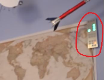
A few Google searches led me to believe it was called a Tix Clock. And if you knew the secret, you could tell what time it is. Unfortunately, they are super hard to find these days as the original manufacturer stopped making them years ago, and the few remaining units scatted around the interwebs command premium prices.
So naturally, I did what any self-respecting engineer would do: I decided to build my own.
The Challenge: Reverse Engineering a Mystery
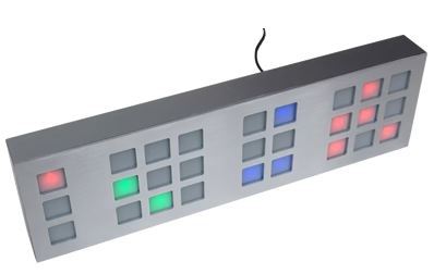
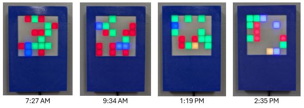
The Tix Clock is beautifully simple in concept yet devilishly clever in execution. Instead of traditional digits, it displays time through a grid of colored lights that appear to change randomly every 15 seconds. The secret? Each grid section represents a different time component:
Simple concept, but implementing it required solving several interesting engineering challenges.
Challenge #1: Mechanical Design and the 3D Printing Nightmare
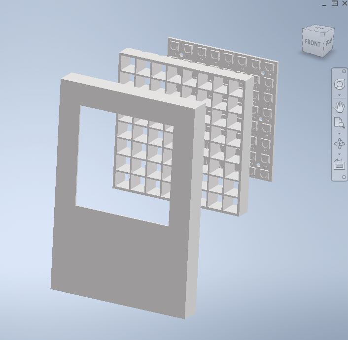
I started by designing the enclosure in Autodesk Inventor, aiming for a clean, modern aesthetic that would look at home in any office. The original Tix Clock had this beautiful minimalist block design that I wanted to emulate while adding my own touches.
My initial design was ambitious, a sleek, single-piece enclosure that would showcase the LED grid perfectly. The problem? My Prusa 3D printer bed wasn’t large enough to accommodate the form factor I wanted, even if printed diagonally! What followed was an exercise in iterative design that any product developer can empathize with.
Eight major iterations. Countless test prints. No matter what I tried, I couldn’t get the Tix Clock format to work with my limited bed space due to print joints ruining the aesthetic or complications with electrical design or wiring.
The breakthrough came when I abandoned the Tix layout approach and designed using a single 8×8 grid (although in the end, only 6×6 was viewable). The final design consists of multiple interlocking components that could now fit comfortably on my print bed while maintaining the aesthetic I was after. Sometimes the best engineering solutions come from embracing constraints rather than fighting them.
I printed everything in PLA partly because that’s what I had on hand, but also because PLA’s ease of printing made it perfect for the tolerances required between the LED grid and the diffusion system.
Challenge #2: Optical Engineering on a Budget
Getting clean, even illumination from a matrix of point-source LEDs is trickier than it sounds. LEDs are incredibly bright directly in front of them but create harsh shadows and hotspots without proper diffusion.
My solution was elegantly simple: two sheets of diffusion paper sandwiched between the outer cover and an internal grid structure. The grid acts as a light guide, channeling each LED’s output through its own compartment and preventing color bleeding between adjacent squares. The diffusion paper then softens the light output, creating that uniform, pleasant glow that makes the time display easy to read without being harsh on the eyes.
This optical system was critical because without proper light management, the color coding would be unreadable, and the entire project would look terrible.
Challenge #3: Hardware Architecture and Power Management
For the LED matrix, I chose an 8×8 WS2812B panel from Amazon. These individually addressable RGB LEDs are perfect for this application as each LED can be set to any color independently and they are controlled through a single data line, although the serpentine routing made addressing specific LEDs a challenge. Even though my design only uses a 6×6 grid, having the extra LEDs gave me flexibility during development and testing.
The brain of the operation is an ESP32-C3 microcontroller. I had one lying around from another project, but it turned out to be perfect for this application. The ESP32-C3 was incredibly overkill for this application, but the built-in WiFi is crucial for NTP time synchronization and firmware OTAs. I ran with FreeRTOS because, why not?
Power management required some consideration. A full 8×8 matrix of WS2812B LEDs can draw significant current at full brightness, so I implemented software-controlled dimming to keep power consumption reasonable. This also made the display easier to view because LEDs at full-brightness would be overwhelming in an office environment.
Challenge #4: Firmware Architecture and the Art of Randomization
The firmware runs on FreeRTOS, which provides the multitasking capabilities needed to handle WiFi connectivity, NTP synchronization, and display updates simultaneously.
The most interesting algorithmic challenge was implementing truly random LED placement. Every 15 seconds, the system needs to redistribute the time-encoded colors across the 6×6 grid in a way that appears completely random to the observer.
My solution uses a linked-list based approach (because when else have you ever used a linked list?). At the start of each randomization cycle, I create a linked list containing the coordinates of all 36 grid positions. Then, for each LED that needs to be placed (determined by the current time), I generated a random index into this list, selected that coordinate and remove it from the list. This ensures that each position can only be used once per cycle, and the selection process is truly random.
// Pseudocode for the randomization algorithm
coordinates_list = create_coordinate_list();
for each color in time_encoding:
    for each LED of this color:
        random_index = generate_random(list_length);
        position = coordinates_list[random_index];
        set_led_at_position(position, color);
        remove_from_list(coordinates_list, random_index);
The time encoding itself is straightforward. The system connects to my WiFi network and synchronizes with NTP server every few hours, ensuring accurate timekeeping without the drift issues that plague many embedded clocks, even with RTCs installed.
Challenge #5: Network Integration
One of the advantages of using the ESP32-C3 is its robust WiFi capabilities. The system automatically connects to my network on startup and maintains periodic synchronization with NTP servers, ensuring it’s always displaying the correct time even after power outages or network interruptions. When network connectivity is temporarily lost, the system falls back to its internal real-time clock while continuously attempting to re-establish NTP synchronization.
Beyond timekeeping, the network connection enables over-the-air firmware updates and remote management through a simple REST API. I can adjust settings, check system status, or push new features without physically accessing the device which is essential for any modern IoT deployment.
The Final Product: More Than Just a Clock
After months of design iteration, component sourcing, and code development, I now have a fully functional Tix(-ish) Clock sitting in my office. Every 15 seconds, it performs its cryptic dance of colors, silently announcing the time to those who know its secret.
But, honestly, this project represents more than just a successful reverse-engineering effort. It showcases the kind of interdisciplinary problem-solving that modern embedded systems development demands: mechanical, firmware, networking, and manufacturing constraints all had to work together seamlessly.
Lessons Learned and Consulting Insights
This project reflects the same types of challenges I regularly help clients solve in my embedded systems consulting work. Whether it’s developing IoT devices, implementing FPGA solutions, or creating custom hardware platforms, the same principles apply:
Constraint-driven design: Sometimes the best solutions come from working within limitations rather than around them. The modular 3D-printed enclosure was actually superior to my original single-piece design.
Systems thinking: Every component affects every other component. The optical design influenced the mechanical design, which influenced the electrical design, which influenced the firmware architecture.
Iterative development: Complex systems require multiple design cycles. Planning for iteration from the start saves time and frustration later.
Robust error handling: Real-world deployment demands bulletproof reliability. Network connectivity, power management, and timing accuracy all required careful consideration.
These are the same challenges facing anyone developing connected devices, industrial controls, or embedded systems. Whether you’re prototyping in a lab or scaling for production, the same core engineering principles apply.
If you’re working on an embedded project that needs this kind of interdisciplinary approach , whether it’s hardware design, FPGA implementation, or IoT connectivity, I’d love to hear about it. Sometimes the most interesting solutions come from the most unexpected constraints.